
Submarine power transmission plays a critical role in modern energy infrastructure. As coastal cities expand and offshore energy projects increase, the demand for reliable underwater power cables continues to grow. Among the most widely used medium-voltage underwater cables is the 15kV Submarine Cable, which provides safe and stable power transmission across seas, rivers, lakes, and offshore installations.
A 15kV submarine cable is designed specifically to operate in harsh underwater environments. These cables must withstand high hydrostatic pressure, corrosion from seawater, mechanical stress during installation, and long-term electrical loading. Because of these requirements, submarine cables are engineered with multiple protective layers and carefully selected conductor sizes.
About structure, specifications, conductor size standards, and practical applications of 15kV submarine cables. We will also provide two important technical tables: one covering metric conductor cross sections from 1 mm² to 800 mm², and another showing ASTM standard conductor sizes from 20 AWG to 1000 MCM.
What Is a 15kV Submarine Cable?
A 15kV submarine cable is a medium-voltage electrical cable specifically designed for underwater installation. It is commonly used to transmit electrical power between locations separated by water such as islands, offshore platforms, coastal substations, and marine renewable energy systems.
The 15kV voltage class is widely used because it offers an ideal balance between insulation thickness, transmission efficiency, and installation cost. Compared with high-voltage submarine cables, a 15kV cable system is easier to manufacture, install, and maintain.
Typical applications include:
- Power supply between mainland and islands
- Offshore oil and gas platform electrification
- Offshore wind farm auxiliary systems
- Port and harbor power distribution
- Coastal industrial facilities
- Subsea pumping and desalination plants
Because of harsh marine conditions, submarine cables require significantly stronger mechanical protection and waterproofing than underground cables.
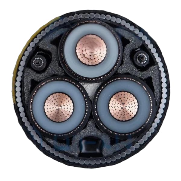
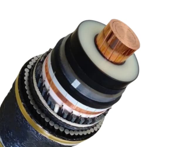
Structural Design of a 15kV Submarine Cable
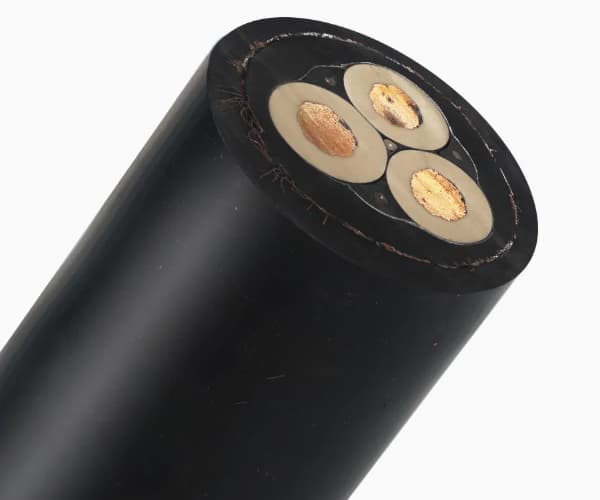
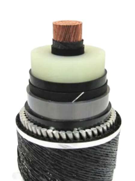
A modern 15kV submarine cable typically consists of several engineered layers. Each layer performs a specific function to ensure electrical reliability and mechanical durability.
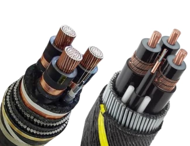
Conductor
The conductor is the core component responsible for carrying electrical current. Most submarine cables use copper conductors because of their high conductivity and excellent mechanical strength. In some applications, aluminum conductors may also be used to reduce weight and cost.
Common conductor constructions include:
- Stranded copper conductor
- Compacted copper conductor
- Aluminum stranded conductor
The conductor cross section is selected based on current carrying capacity and transmission distance.
Conductor Screen
A semiconductive conductor screen surrounds the conductor. This layer smooths the electric field and eliminates air gaps between the conductor and insulation.
Insulation Layer
The insulation is one of the most critical components of a submarine cable. For 15kV cables, the most widely used insulation materials are:
- XLPE (Cross-Linked Polyethylene)
- EPR (Ethylene Propylene Rubber)
XLPE insulation offers excellent dielectric strength, thermal resistance, and long service life, making it the preferred choice for many submarine cable systems.
Insulation Shield
The insulation shield is another semiconductive layer placed over the insulation. It maintains uniform electric field distribution and protects the insulation from electrical stress.
Metallic Shield
A metallic shielding layer is typically applied to provide grounding and fault current return paths. Common materials include copper tape or copper wires.
Water Blocking System
Submarine cables must prevent water from penetrating into the cable core. Therefore, water blocking materials are added, including:
- Water swelling tapes
- Water blocking powders
- Longitudinal sealing compounds
These materials stop water migration if the cable sheath becomes damaged.
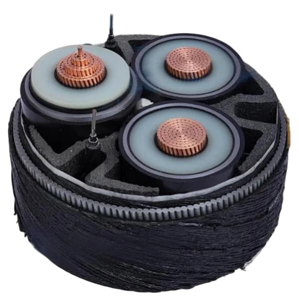
Armoring Layer
Mechanical protection is essential for submarine cables. Steel wire armoring protects the cable from:
- Fishing gear
- Ship anchors
- Seabed abrasion
- Installation tension
Shallow water cables may use double steel wire armor, while deep-water cables often use single armor layers.
Outer Sheath
The outer sheath protects the cable from corrosion and environmental damage. The most common materials include:
- Polyethylene (PE)
- High-density polyethylene (HDPE)
- PVC in some designs
HDPE is particularly resistant to seawater and abrasion.
Conductor Cross Section Table (Metric System 1 mm² – 800 mm²)
Below is a reference table showing common conductor cross sections used in medium-voltage submarine cables.
| Conductor Size (mm²) | Approx Diameter (mm) | Estimated Current Capacity (A) |
|---|---|---|
| 1 | 1.13 | 15 |
| 2.5 | 1.78 | 25 |
| 4 | 2.25 | 35 |
| 6 | 2.76 | 45 |
| 10 | 3.57 | 65 |
| 16 | 4.51 | 85 |
| 25 | 5.64 | 110 |
| 35 | 6.68 | 135 |
| 50 | 7.98 | 170 |
| 70 | 9.45 | 215 |
| 95 | 11.0 | 260 |
| 120 | 12.4 | 300 |
| 150 | 13.8 | 340 |
| 185 | 15.3 | 385 |
| 240 | 17.5 | 450 |
| 300 | 19.5 | 510 |
| 400 | 22.6 | 600 |
| 500 | 25.2 | 690 |
| 630 | 28.3 | 780 |
| 800 | 31.9 | 900 |
Actual current capacity depends on cable design, installation depth, seabed temperature, and cooling conditions.
ASTM Conductor Size Table (20 AWG – 1000 MCM)
In North America and many international engineering specifications, conductor sizes follow the ASTM AWG / MCM standard.
| AWG / MCM | Cross Section (mm²) | Conductor Diameter (mm) |
|---|---|---|
| 20 AWG | 0.52 | 0.81 |
| 18 AWG | 0.82 | 1.02 |
| 16 AWG | 1.31 | 1.29 |
| 14 AWG | 2.08 | 1.63 |
| 12 AWG | 3.31 | 2.05 |
| 10 AWG | 5.26 | 2.59 |
| 8 AWG | 8.37 | 3.26 |
| 6 AWG | 13.3 | 4.11 |
| 4 AWG | 21.2 | 5.19 |
| 3 AWG | 26.7 | 5.83 |
| 2 AWG | 33.6 | 6.54 |
| 1 AWG | 42.4 | 7.35 |
| 1/0 AWG | 53.5 | 8.25 |
| 2/0 AWG | 67.4 | 9.27 |
| 3/0 AWG | 85.0 | 10.4 |
| 4/0 AWG | 107 | 11.7 |
| 250 MCM | 127 | 12.7 |
| 350 MCM | 177 | 15.0 |
| 500 MCM | 253 | 18.0 |
| 750 MCM | 380 | 22.0 |
| 1000 MCM | 507 | 25.4 |
This table helps engineers convert between AWG and metric conductor sizes when designing cable systems.
Applications of 15kV Submarine Cable
Medium-voltage submarine cables are widely used in many marine infrastructure projects.
Island Power Interconnection
Many islands receive electricity from mainland grids through submarine cables. This approach eliminates the need for costly diesel power generation.
Offshore Oil and Gas Platforms
Subsea cables supply power to drilling rigs, pumping stations, and offshore processing facilities.
Offshore Wind Farms
Wind turbines generate electricity offshore and transmit power to substations using submarine cable systems.
Port and Harbor Infrastructure
Ports require stable electrical supply for cranes, ship docking systems, and logistics facilities.
Installation of Submarine Cables
The installation process is complex and requires specialized equipment.
Cable Laying Vessels
Cable laying ships transport and deploy submarine cables along planned seabed routes.
Seabed Burial
To protect cables from mechanical damage, they are often buried 1–3 meters below the seabed using jetting or ploughing techniques.
Mechanical Protection
In rocky areas where burial is impossible, engineers may install protective rock layers or concrete mattresses.
Advantages of Modern 15kV Submarine Cable Systems
Modern submarine cable technologies offer several benefits.
High reliability: Designed service life can exceed 30–40 years.
Strong environmental resistance: Advanced materials resist seawater corrosion.
Stable electrical performance: High-quality insulation ensures long-term safety.
Mechanical durability: Steel armoring protects cables from external damage.
These advantages make submarine cables essential infrastructure for marine energy systems.
15kV Submarine Cable
The 15kV Submarine Cable is an essential component of medium-voltage underwater power transmission networks. It plays a key role in connecting islands, offshore facilities, and coastal energy systems.
This guide introduced the structural design of submarine cables, explained their main applications, and provided two important conductor reference tables:
- Metric conductor sizes from 1 mm² to 800 mm²
- ASTM conductor sizes from 20 AWG to 1000 MCM
Selecting the correct conductor size and cable structure ensures efficient power transmission, long service life, and reliable operation in challenging marine environments.
As offshore energy infrastructure continues to expand worldwide, 15kV submarine cables will remain a crucial technology supporting the global transition toward reliable and sustainable energy systems.