
Reliable power transmission depends on strong and stable connections. In high-voltage systems, one of the most critical interfaces sits between underground cables and gas-insulated switchgear. At this point, ال GIS Termination plays a decisive role. At the 132kV level, even minor design or installation issues can lead to serious failures. لذلك, engineers pay close attention to every detail of this component.
As cities continue to expand, substations often move underground or into compact spaces. بالتالي, gas-insulated switchgear (نظم المعلومات الجغرافية) becomes more common. في نفس الوقت, utilities demand higher reliability and lower maintenance. لهذا السبب, the demand for high-quality 132kV cable GIS termination solutions continues to grow.
What Is a GIS Termination?
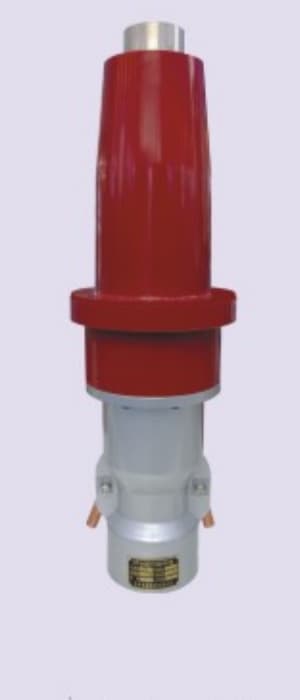
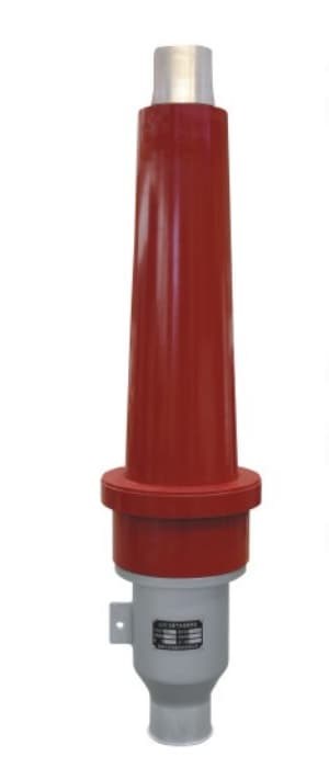
أ GIS Termination connects a high-voltage cable to gas-insulated switchgear. It creates a controlled transition from the cable insulation system, usually XLPE, into the SF₆ gas environment inside the GIS.
لكن, this transition is not simple. The electric field changes significantly at the interface. نتيجة ل, engineers must carefully manage electrical stress, maintain insulation performance, and prevent partial discharge.
In practical terms, a GIS termination allows electricity to flow safely and efficiently from the cable into the switchgear. Without this controlled interface, system stability would quickly degrade.
Why 132kV GIS Cable Termination Is Important
In modern power systems, reliability remains the top priority. A failure at the termination point can shut down an entire substation and disrupt supply.
أولاً, GIS terminations support compact substation layouts. Because GIS equipment uses enclosed gas insulation, it requires far less space than traditional air-insulated systems. لذلك, it suits dense urban environments.
ثانية, they improve operational reliability. The sealed structure protects internal components from dust, رُطُوبَة, and pollution. فضلاً عن ذلك, it reduces the impact of environmental conditions.
علاوة على ذلك, a properly designed 132kV GIS termination minimizes electric stress concentration. نتيجة ل, both the cable and the switchgear can operate safely over a longer service life.
Main Components of a 132kV GIS Termination
A GIS termination includes several essential components. Each one contributes to electrical stability and mechanical strength.
نظام التحكم في الإجهاد
To begin with, the stress control system manages the electric field at the cable end. Without proper control, the field becomes uneven and may cause insulation failure. لذلك, engineers use stress cones or field grading materials to distribute the electric field evenly.
Insulating Body
التالي, the insulating body provides the primary dielectric barrier. It separates the high-voltage conductor from the grounded GIS enclosure. عادة, manufacturers use silicone rubber or epoxy resin because these materials offer strong insulation and thermal stability.
اتصال الموصل
في نفس الوقت, the conductor must connect securely to the GIS terminal. A reliable connection reduces resistance and prevents overheating. في معظم الحالات, technicians use compression or bolted connectors to achieve this.
Sealing System
في أثناء, the sealing system prevents SF₆ gas leakage and blocks moisture ingress. Because GIS depends on stable gas pressure, effective sealing remains essential for long-term performance.
Flange and Housing
أخيراً, the flange connects the termination to the GIS equipment, while the housing protects internal components from mechanical damage. معاً, these parts ensure proper alignment and durability.
Types of GIS Termination for 132kV Cables
Different applications require different designs. لذلك, engineers select the appropriate type based on project conditions.
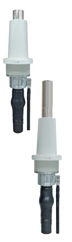
Dry Type GIS Termination
In many modern substations, dry type terminations are preferred. They use solid insulation materials instead of oil. نتيجة ل, they offer easier maintenance and reduced environmental risk.
Oil-Filled GIS Termination
على الجانب الآخر, oil-filled terminations provide excellent insulation performance. لكن, they require careful sealing and regular maintenance. لذلك, they are less common in newer installations.
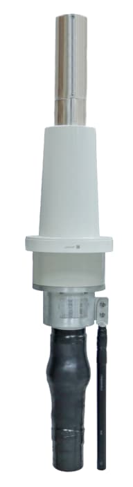
Plug-In GIS Termination
فضلاً عن ذلك, plug-in terminations allow faster installation. Because of their modular design, they reduce downtime and improve efficiency, especially in prefabricated GIS systems.
Cable Conductor Size Table (25 ملم² إلى 3000 مم²)
When selecting a GIS Termination, conductor size becomes a key factor. It influences current capacity, thermal behavior, and mechanical compatibility. لذلك, engineers must evaluate cable size carefully.
Conductor Cross-Section and Technical Parameters
| حجم الموصل (مم²) | تقريبا. الفريق العامل المخصص/مليون متر مكعب | قطر الموصل (مم) | مقاومة العاصمة (Ω/km @20°C) | Typical Current Capacity (أ) | Application Level |
|---|---|---|---|---|---|
| 25 | 4 الفريق العامل المخصص | 5.6 | 0.727 | 150–180 | يتحكم / small load |
| 35 | 2 الفريق العامل المخصص | 6.7 | 0.524 | 180–220 | Light distribution |
| 50 | 1/0 الفريق العامل المخصص | 8.0 | 0.387 | 220–270 | Distribution |
| 70 | 2/0 الفريق العامل المخصص | 9.6 | 0.268 | 260–320 | Medium load |
| 95 | 3/0 الفريق العامل المخصص | 11.0 | 0.193 | 300–370 | Substation feeder |
| 120 | 4/0 الفريق العامل المخصص | 12.4 | 0.153 | 340–420 | Medium HV |
| 150 | 300 مليون متر مكعب | 13.9 | 0.124 | 380–470 | Transmission |
| 185 | 350 مليون متر مكعب | 15.5 | 0.099 | 420–520 | Transmission |
| 240 | 500 مليون متر مكعب | 17.5 | 0.075 | 480–600 | 132kV standard |
| 300 | 600 مليون متر مكعب | 19.5 | 0.060 | 550–680 | Main feeder |
| 400 | 800 مليون متر مكعب | 22.6 | 0.047 | 650–800 | Heavy load |
| 500 | 1000 مليون متر مكعب | 25.2 | 0.036 | 750–920 | HV transmission |
| 630 | 1250 مليون متر مكعب | 28.3 | 0.028 | 850–1050 | Common 132kV |
| 800 | 1600 مليون متر مكعب | 31.9 | 0.022 | 1000–1200 | Bulk power |
| 1000 | 2000 مليون متر مكعب | 35.7 | 0.017 | 1150–1400 | Large substations |
| 1200 | 2500 مليون متر مكعب | 39.1 | 0.015 | 1300–1550 | Grid backbone |
| 1400 | — | 42.2 | 0.013 | 1400–1700 | Extra heavy load |
| 1600 | — | 45.2 | 0.011 | 1550–1850 | Large transmission |
| 2000 | — | 50.5 | 0.009 | 1750–2100 | Major grid |
| 2500 | — | 56.4 | 0.007 | 2000–2400 | Ultra high demand |
| 3000 | — | 61.8 | 0.006 | 2200–2600 | Extreme capacity |
How Conductor Size Affects GIS Termination Design
Conductor size directly influences the design of a GIS termination. أولاً, larger conductors require stronger mechanical support. نتيجة ل, the termination must handle higher weight and installation stress.
فضلاً عن ذلك, electric field distribution changes with conductor size. لذلك, engineers must adjust stress control components to maintain uniform field grading.
بالإضافة إلى, higher current leads to increased heat generation. بالتالي, thermal management becomes more critical for large cross-section cables.
أخيراً, installation becomes more complex as cable size increases. على سبيل المثال, larger cables require greater bending radius and specialized handling.
Typical Sizes Used in 132kV Systems
في الممارسة العملية, only a limited range of sizes appears frequently. Most utilities prefer standardized options for efficiency and cost control.
Common conductor sizes include:
- 240 مم²
- 300 مم²
- 400 مم²
- 630 مم²
- 800 مم²
- 1000 مم²
Among these, 630 mm² and 800 mm² provide a strong balance between capacity and economic performance. لذلك, they are widely used in transmission projects.
Installation of 132kV GIS Termination
Proper installation determines long-term reliability. لهذا السبب, technicians must follow strict procedures at every stage.
أولاً, they prepare the cable by removing the outer sheath and insulation layers carefully. At this stage, cleanliness is essential.
التالي, they install stress control components and insulation parts. ثم, they connect the conductor and assemble the termination body.
بعد ذلك, they mount the termination onto the GIS flange and complete sealing. أخيراً, engineers perform testing, including partial discharge and high-voltage withstand tests.
Common Challenges and Practical Solutions
Working with GIS terminations presents several challenges. لكن, proper practices can effectively address them.
Electrical stress concentration may occur if installation lacks precision. لذلك, technicians must follow design guidelines closely.
Moisture ingress can reduce insulation performance. To prevent this, teams must control humidity during installation.
Gas leakage also poses risks. High-quality sealing systems help avoid this issue.
فضلاً عن ذلك, mechanical misalignment can cause long-term problems. Accurate positioning ensures stable operation.
Advantages of GIS Cable Termination
GIS terminations offer several advantages in modern power systems. أولاً, they support compact designs suitable for urban environments.
علاوة على ذلك, they operate reliably within sealed systems. نتيجة ل, they resist environmental factors such as dust and humidity.
فضلاً عن ذلك, they require less maintenance compared to traditional systems. لذلك, utilities can reduce operational costs over time.
Applications of 132kV GIS Termination
132kV GIS terminations are widely used across various sectors. على سبيل المثال, they play a key role in:
- Urban underground substations
- Industrial power distribution systems
- Renewable energy grid connections
- Infrastructure projects such as railways and airports
As infrastructure continues to grow, these applications expand further.
132kV Cable GIS Termination manufacturer
أ 132kV Cable GIS Termination serves as a critical link in high-voltage transmission systems. It connects cables to gas-insulated switchgear while ensuring electrical safety and reliability.
From component design to conductor size selection, every detail affects performance. لذلك, engineers must evaluate each factor carefully.
As power networks evolve, GIS technology continues to gain importance. بالتالي, selecting the right GIS termination solution—and matching it with the appropriate cable size—remains essential for long-term success from 132kV Cable GIS Termination.