
1. Introduction to 110kV Cable GIS Termination
A 110kV cable GIS termination is an important accessory in high-voltage power transmission systems. It connects XLPE power cables to gas-insulated switchgear (GIS) and provides a safe, reliable electrical connection.
今日, many power substations use GIS technology. Compared with traditional air-insulated switchgear (AIS), GIS requires less installation space. It also offers good protection against environmental conditions and helps improve the reliability of electrical systems.
しかし, connecting a high-voltage cable to GIS equipment requires a special cable termination. The termination must provide reliable insulation, control the electric field, and ensure a secure connection between the cable conductor and the GIS conductor.
A 110kV GIS cable termination is commonly used in underground power transmission, urban substations, 産業施設, 再生可能エネルギープロジェクト, and power generation plants.
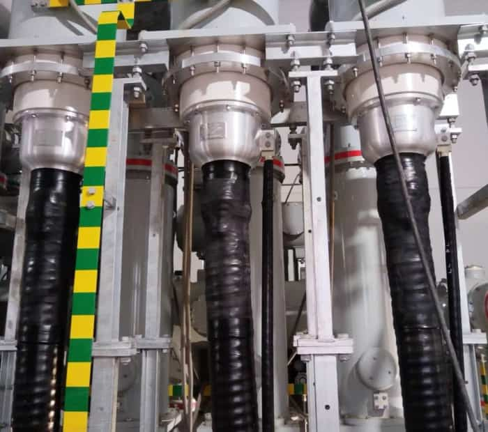
2. What Is a 110kV Cable GIS Termination?
A 110kV cable GIS termination is a high-voltage cable accessory designed to connect an XLPE power cable to gas-insulated switchgear.
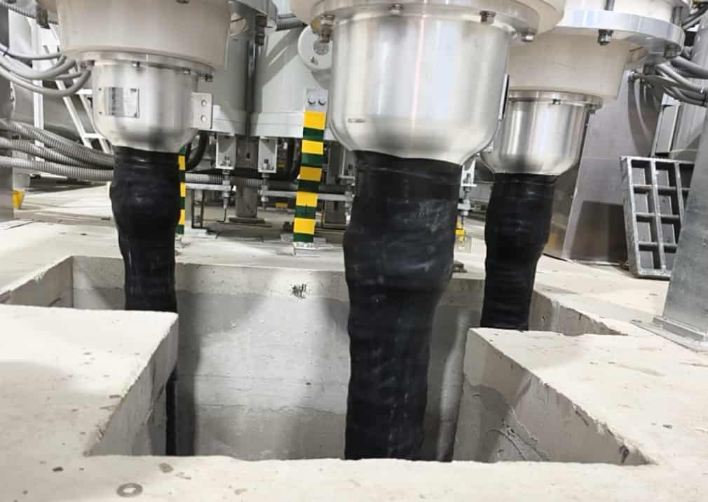
Unlike an outdoor cable termination, which uses an external insulating housing with sheds, a GIS termination connects directly to a dedicated cable connection compartment inside the GIS equipment.
The termination provides three main functions.
Electrical connection: It connects the cable conductor to the GIS conductor through a suitable contact system.
Electric field control: It controls the electric field around the cable insulation and the connection area. This helps prevent partial discharge and electrical breakdown.
Insulation protection: It provides reliable insulation between the energized conductor and grounded metal parts of the GIS enclosure.
Most 110kV GIS cable terminations use a prefabricated insulation system. デザインによっては, they may also use a plug-in connection with a separable interface.
For IEC-based 110kV systems, the maximum equipment voltage is commonly 123kV (Um = 123kV). したがって, engineers should select the GIS termination according to the actual system voltage and project requirements.
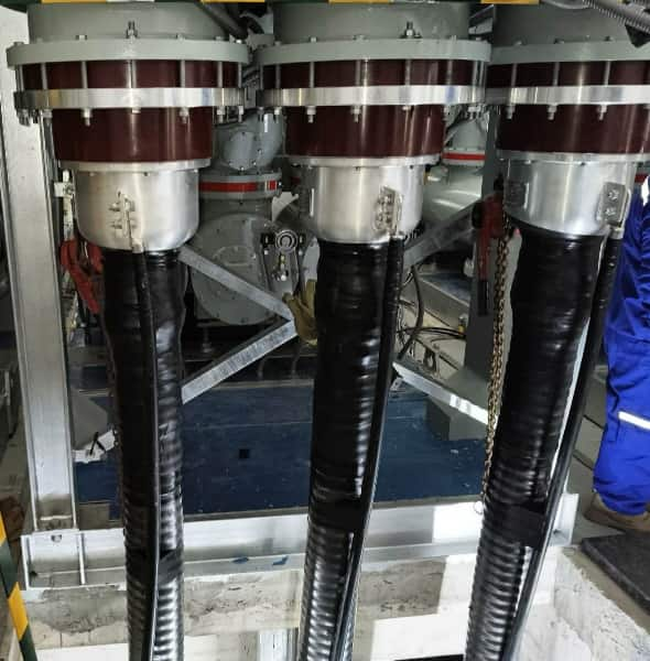
3. Main Components of a 110kV GIS Cable Termination
A 110kV GIS cable termination contains several important components. Each component has a specific role in maintaining electrical and mechanical performance.
3.1. 導体コネクタ
The conductor connector joins the cable conductor to the GIS electrical contact.
Manufacturers usually design the connector for copper or aluminum conductors. Its size and structure depend on the cable cross-section and GIS connection design.
A good conductor connector should provide:
- Low electrical contact resistance.
- 高い導電性.
- Reliable mechanical connection.
- 優れた熱性能.
- Suitable short-circuit current capacity.
加えて, the connector must match the GIS contact system. したがって, engineers should confirm the connection dimensions before ordering.
3.2. Electric Field Stress Control System
Electric field control is one of the most important parts of a high-voltage GIS termination.
When the semiconductive screen of an XLPE cable ends, the electric field changes around the insulation. This change can create high electrical stress near the screen cut.
To reduce this stress, the termination uses a special field control system. It helps distribute the electric field more evenly.
デザインによっては, manufacturers may use a prefabricated stress cone or other field control components.
A well-designed stress control system helps reduce partial discharge and improves the long-term performance of the termination.
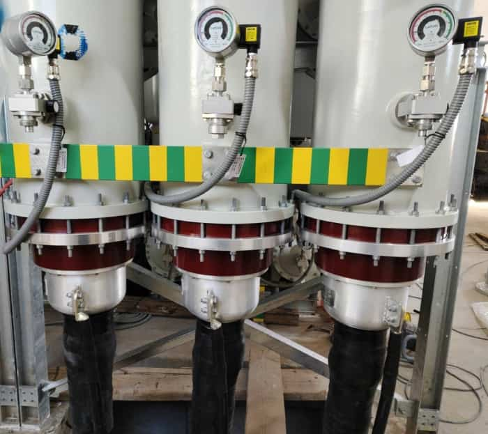
3.3. Main Insulation Body
The main insulation body provides electrical insulation between the high-voltage conductor and grounded components.
Most modern 110kV GIS cable terminations use prefabricated elastomeric insulation components, such as silicone rubber or EPDM-based materials.
These materials offer good electrical properties and flexibility. They also help maintain close contact with the prepared cable insulation.
The insulation body must match the cable insulation diameter and the required electrical design.
3.4. Epoxy Resin Insulating Bushing
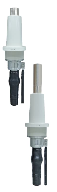
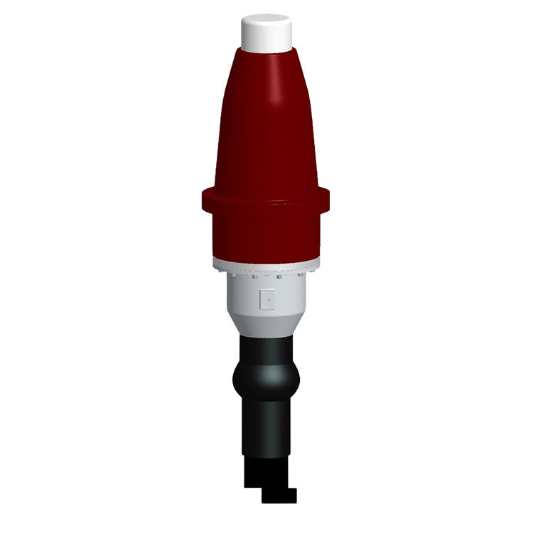
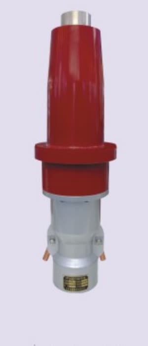
The epoxy resin bushing is an important part of many GIS cable connection systems.
It provides electrical insulation between the energized contact and the grounded GIS enclosure. It also forms the interface between the cable termination and the GIS compartment.
The bushing must meet the electrical and mechanical requirements of the GIS equipment.
その寸法, contact arrangement, and interface design must match the GIS manufacturer’s specifications.
3.5. Plug-in Connection System
Many modern 110kV GIS cable terminations use a plug-in connection design.
This system allows the cable termination to connect with the GIS bushing through a specially designed contact interface.
The plug-in design offers several advantages:
- Compact connection structure.
- Reliable electrical contact.
- Reduced exposure of live parts.
- Convenient connection and disconnection during planned maintenance.
- Good insulation performance.
しかし, the connection interface must match the GIS equipment. Even small differences in dimensions may affect installation and electrical performance.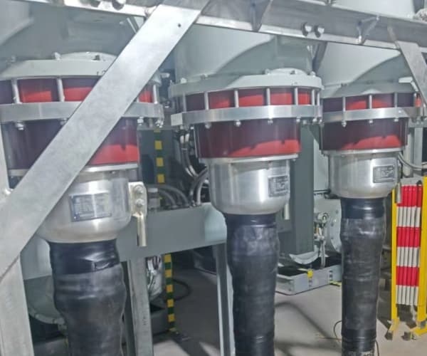
3.6. Grounding and Sealing Components
The grounding system connects the cable metallic screen to the designated grounding arrangement.
The actual method depends on the cable bonding design. Common options include single-point bonding, 両端ボンディング, and cross-bonding.
その間, sealing components prevent moisture and foreign materials from entering the cable termination.
Proper sealing helps protect the insulation system and maintain reliable operation.
4. Types of 110kV GIS Cable Terminations
Different GIS connection designs are available for high-voltage cable systems. The correct choice depends on the GIS structure, cable design, およびプロジェクトの要件.
4.1. Plug-in GIS Cable Termination
Plug-in GIS cable terminations are widely used in modern high-voltage substations.
They use a special connection interface to join the cable termination to the GIS bushing.
The design provides a compact connection and reduces the need for exposed high-voltage conductors.
さらに, the prefabricated structure helps improve installation consistency.
しかし, the plug-in interface must match the GIS equipment. Buyers should confirm the interface drawing with both the GIS supplier and cable accessory manufacturer.
4.2. 乾式 GIS ケーブル終端
Dry-type GIS cable terminations use solid insulation materials to provide the required electrical insulation.
They do not rely on an oil-filled insulation chamber in the cable termination itself.
デザインによっては, the termination may use prefabricated silicone rubber insulation and an epoxy resin bushing.
Dry-type designs can reduce the need for liquid insulation handling. They are also suitable for many modern GIS connection systems.
4.3. オイル封入 GIS ケーブル終端
Some older or special GIS cable connection designs use oil-filled insulation structures.
These products use insulating oil to provide electrical insulation in the relevant components.
しかし, the design may require additional sealing and oil management.
したがって, buyers should confirm the insulation type and connection arrangement with the GIS manufacturer before selecting a termination.
5. Technical Specifications of 110kV GIS Cable Terminations
The technical specifications of a 110kV GIS cable termination depend on the cable dimensions, GISインターフェース, 絶縁レベル, and electrical requirements.
For many IEC-based 110kV systems, the maximum equipment voltage is 123kV.
The following table shows typical reference specifications.
| パラメータ | Technical Specification |
|---|---|
| 製品名 | 110kV GIS ケーブル終端 |
| Rated System Voltage | 110kV |
| Maximum Equipment Voltage | 123kV |
| Rated Frequency | 50Hz / 60Hz |
| ケーブルの種類 | XLPE Power Cable |
| 導体材質 | 銅 / アルミニウム |
| Conductor Cross-Section | According to project |
| 主絶縁体 | Prefabricated Insulation System |
| 断熱材 | シリコーンゴム / Other Approved Materials |
| GIS Connection | Plug-in Type |
| GIS Bushing | Epoxy Resin |
| 設置場所 | Indoor GIS Compartment |
| Electric Field Control | ストレスコントロールシステム |
| 適用規格 | IEC 60840 / IEC 62271-209 |
These specifications are for general reference. The actual product design must match the GIS interface drawing and cable data sheet.
Engineers should also check the insulation dimensions, conductor connection, impulse withstand voltage, power frequency withstand voltage, and partial discharge requirements.
6. International Standards for 110kV GIS Cable Terminations
International standards help ensure the safety and reliability of high-voltage cable accessories and GIS connection systems.
Two important standards are IEC 60840 およびIEC 62271-209.
6.1. IEC 60840
The full title of IEC 60840 is:
Power cables with extruded insulation and their accessories for rated voltages above 30 kV (1 つ = 36 kV) まで 150 kV (1 つ = 170 kV) – Test methods and requirements.
This standard covers XLPE power cables and their accessories, including cable joints and terminations.
It includes requirements for:
- Electrical type tests.
- 定期テスト.
- 部分放電試験.
- AC耐電圧試験.
- Lightning impulse voltage tests.
- Tests after installation.
For a typical 110kV cable system with Um = 123kV, IEC 60840 provides an important reference for cable termination design and testing.
6.2. IEC 62271-209
IEC 62271-209 covers cable connections for gas-insulated metal-enclosed switchgear with rated voltages above 52kV.
This standard is particularly important for GIS cable termination systems.
It addresses the cable connection interface between the cable termination and the GIS equipment.
したがって, engineers should pay close attention to interface compatibility when selecting a 110kV GIS cable termination.
6.3. IEC 60270
IEC 60270 covers partial discharge measurement techniques.
Partial discharge testing helps identify insulation defects that may affect the long-term performance of high-voltage cable accessories.
結果として, it plays an important role in checking the electrical quality of GIS cable terinations.
7. Installation Process of a 110kV GIS Cable Termination
Correct installation is essential for the safe operation of a 110kV GIS cable system.
Even a high-quality GIS termination may fail if technicians prepare the cable incorrectly. したがって, qualified technicians must follow the manufacturer’s installation manual.
ステップ 1: Check the Cable and GIS Interface
設置前, technicians should check the cable dimensions and GIS connection drawings.
Important cable information includes:
- 導体断面積.
- 導体径.
- XLPE insulation diameter.
- 断熱材の厚さ.
- Metallic screen structure.
- アウターシース径.
同時に, the installation team must confirm the GIS bushing interface and connection dimensions.
ステップ 2: ケーブルを準備する
Technicians remove the outer sheath, 金属スクリーン, and semiconductive layers according to the installation instructions.
They must control the cutting dimensions carefully. さらに重要なことは, they should avoid damaging the XLPE insulation.
ステップ 3: Prepare the XLPE Insulation Surface
The XLPE insulation surface must be smooth, クリーン, and dry.
Technicians should remove dust, grease, and other foreign materials. They must also check for scratches and sharp edges.
Good surface preparation helps maintain reliable contact between the cable insulation and the termination body.
ステップ 4: Install the Stress Control Components
次, technicians install the stress control components at the specified position.
Correct positioning is essential because the components control the electric field around the cable screen cut.
The installation team should check all dimensions before moving to the next step.
ステップ 5: Install the Main Insulation Body
Technicians then install the prefabricated insulation body.
They must follow the manufacturer’s instructions to ensure correct positioning and proper contact with the XLPE insulation.
Any contamination or incorrect assembly may affect the insulation performance.
ステップ 6: Connect the GIS Interface
After preparing the termination, technicians connect it to the GIS bushing.
They must check the conductor contact, mechanical connection, and interface alignment.
The GIS compartment must also meet the required cleanliness and assembly conditions.
ステップ 7: Complete Grounding and Sealing
The installation team connects the cable metallic screen according to the approved grounding design.
They also check all sealing components to prevent moisture and foreign materials from entering the connection system.
ステップ 8: Perform Electrical Tests
ついに, the complete cable system must pass the electrical tests required by the project.
These tests may include AC voltage withstand tests and partial discharge measurements.
The test methods and voltage levels must follow the applicable standards and approved project documents.
8. Applications of 110kV GIS Cable Terminations
110kV GIS cable terminations are widely used in modern power transmission systems.
8.1. Urban Power Substations
Urban substations often have limited installation space.
GIS equipment provides a compact solution for these locations. その間, 110kV GIS cable terminations connect underground cables to the GIS equipment.
8.2. 再生可能エネルギープロジェクト
Wind farms and large solar power plants need reliable connections to the main power grid.
例えば, 110kV cable systems may connect renewable energy substations to regional transmission networks.
GIS cable terminations provide the required high-voltage connection.
8.3. Industrial Power Plants
Large industrial facilities need stable power supplies.
採掘作業, petrochemical plants, 製鉄所, and manufacturing facilities may use 110kV GIS equipment in their power systems.
Reliable cable terminations help maintain safe and stable electrical connections.
8.4. Underground Power Transmission
Many cities use underground cables to reduce the need for overhead transmission lines.
These systems often connect to GIS substations because GIS equipment requires less space.
したがって, 110kV GIS cable terminations play an important role in underground power transmission.
8.5. Power Generation Facilities
火力発電所, hydropower stations, and other generation facilities use GIS equipment in their electrical systems.
A suitable GIS cable termination connects high-voltage cables to the switchgear and helps transfer electrical energy safely.
9. How to Choose a Reliable 110kV GIS Termination Manufacturer
Selecting a reliable manufacturer is important for every high-voltage power project.
EPC請負業者, power utilities, engineering companies, and cable distributors should consider the following factors.
1. 定格電圧
初め, confirm the rated system voltage and maximum equipment voltage.
For many IEC-based 110kV systems, the maximum equipment voltage is 123kV.
2. GIS Interface Compatibility
This is one of the most important factors.
The termination must match the GIS bushing interface. Buyers should provide the GIS manufacturer’s drawings and technical specifications before ordering.
3. ケーブルの互換性
The termination must match the cable conductor size, 絶縁体直径, and cable structure.
したがって, buyers should provide a complete cable data sheet.
4. Insulation Design
Check the main insulation material, stress control system, and electrical design.
The manufacturer should provide technical information to show that the product meets the project requirements.
5. Electrical Test Reports
Ask for relevant type test reports and routine test records.
These documents help confirm product quality and compliance with the applicable standards.
6. 導入サポート
A professional manufacturer should provide installation manuals, 技術的な図面, and engineering support.
This service helps reduce installation errors and improve project efficiency.
7. 製造経験
High-voltage GIS terminations require accurate design and strict quality control.
したがって, buyers should review the manufacturer’s technical experience, production facilities, and quality management procedures.
10. Frequently Asked Questions About 110kV GIS Cable Terminations
Q1. What is the difference between a 110kV GIS termination and an outdoor cable termination?
A GIS termination connects an XLPE cable to gas-insulated switchgear through a dedicated connection interface.
An outdoor termination connects the cable to outdoor electrical equipment and uses an external insulating housing with sheds.
したがって, the two products have different structures and installation requirements.
第2四半期. What is the maximum equipment voltage for a 110kV GIS termination?
For many IEC-based 110kV systems, the maximum equipment voltage is 123kV (Um = 123kV).
しかし, buyers should confirm the project voltage requirements before ordering.
Q3. What is the function of the epoxy bushing in a GIS termination?
The epoxy bushing provides electrical insulation between the energized contact and the grounded GIS enclosure.
It also forms an important part of the cable connection interface.
Q4. Is a 110kV GIS cable termination dry-type or oil-filled?
The answer depends on the product design.
Many modern GIS cable terminations use dry-type prefabricated insulation systems. しかし, some special or older designs may use oil-filled structures.
Buyers should confirm the insulation design with the manufacturer.
Q5. Which standards apply to 110kV GIS cable terminations?
IEC 60840 covers high-voltage XLPE cables and their accessories.
IEC 62271-209 covers cable connections for gas-insulated metal-enclosed switchgear with rated voltages above 52kV.
Both standards are important references for 110kV GIS cable connection projects.
Q6. Can a 110kV GIS termination connect copper and aluminum cables?
はい. Manufacturers can design GIS cable terminations for both copper and aluminum conductors.
しかし, the conductor connector must match the conductor material, 寸法, and GIS contact arrangement.
Q7. What information is needed to select a 110kV GIS termination?
Buyers should provide the cable data sheet, conductor cross-section, 絶縁体直径, GIS interface drawing, 定格電圧, およびプロジェクトの要件.
With this information, the manufacturer can check compatibility and prepare a suitable technical proposal.
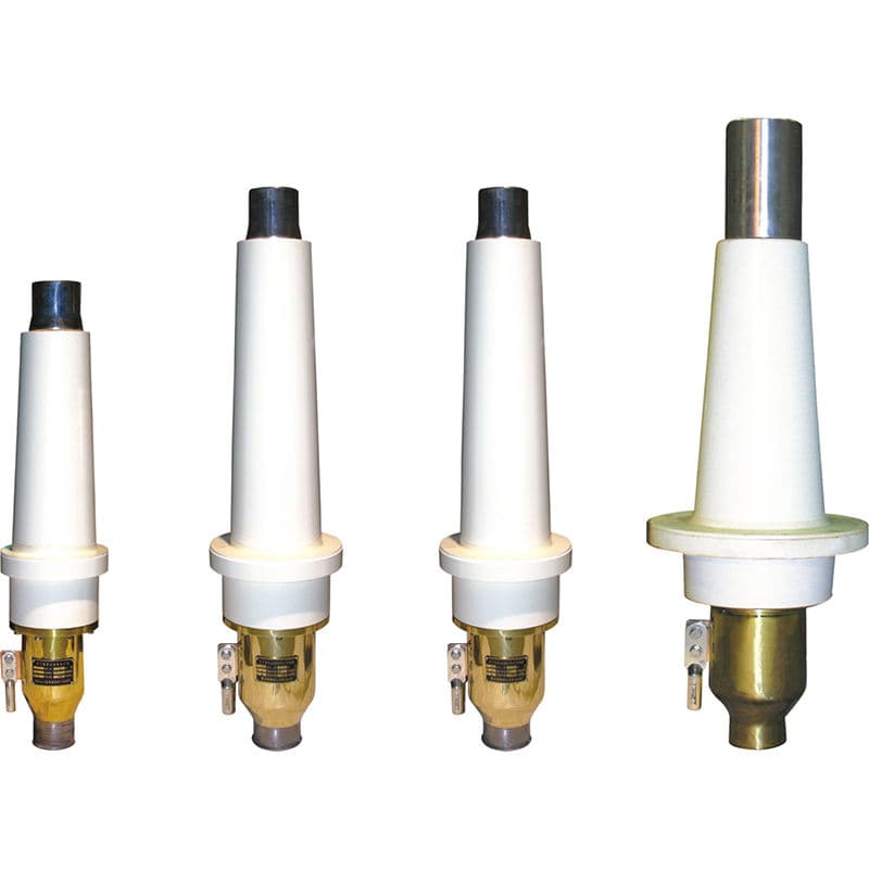
11. Dosense Cable – 110kV Cable GIS Termination Manufacturer
Dosense Cable is a manufacturer of high-voltage power cables and cable accessories for international power transmission and distribution projects.
As a supplier of 110kV cable GIS termination solutions, Dosense Cable focuses on providing products for high-voltage XLPE cable systems.
Our technical solutions can be developed according to different cable structures, 導体材料, cross-sections, and GIS interface requirements.
We understand that every GIS project has specific electrical and mechanical requirements. したがって, interface compatibility, 電界制御, 断熱性能, and reliable conductor connections are important parts of our product design.
In addition to 110kV GIS cable terminations, Dosense Cable also provides outdoor cable terminations, high-voltage cable joints, and other power cable accessories.
Whether you are an EPC contractor, electrical utility, engineering company, or cable distributor, Dosense Cable can support your project with technical information and customized product solutions.
Contact Dosense Cable today to discuss your 110kV Cable GIS Termination requirements. Request technical drawings, 製品仕様, and a competitive quotation for your next high-voltage power project.