
Introduction to 110kV Cable Joint
A 110kV cable joint is an essential accessory in high-voltage power transmission systems. It connects two sections of high-voltage cables and ensures reliable electrical insulation, protection mécanique, and current transmission. In underground power networks, a high-quality cable joint helps maintain a stable connection and reduces the risk of electrical failure.
Aujourd'hui, many power transmission projects use 110kV XLPE cables. These cables are widely installed in cities, installations industrielles, sous-stations, centrales électriques, et projets d'énergies renouvelables. Cependant, cable routes often require several cable sections. Donc, engineers need reliable 110kV cable joints to connect these sections safely.
A 110kV cable joint must provide excellent insulation performance. It must also control the electric field around the conductor connection. En outre, it needs to protect the cable insulation and metallic sheath from moisture, eau, et dommages mécaniques.
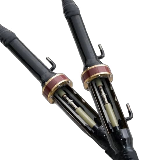
What Is a 110kV Cable Joint?
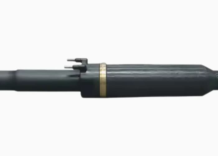
A 110kV cable joint, also called a 110kV cable splice, is a high-voltage cable accessory used to connect two cable sections. It restores the electrical and mechanical properties of the cable at the connection point.
For a typical 110kV XLPE cable system, the cable joint must connect the following components:
- Conducteur
- Isolation XLPE
- Écran conducteur
- Écran d'isolation
- Metallic screen or metallic sheath
- Gaine de protection extérieure
Each component has a specific function. The joint must reconnect the conductors and rebuild the insulation system. It must also provide reliable electrical stress control.
In many 110kV power systems, the rated voltage is 64/110kV, with a maximum system voltage of 123kV (Un). Donc, the cable joint design must match the electrical requirements of the complete cable system.
A suitable 110kV XLPE cable joint is not simply a mechanical connector. It is a carefully designed high-voltage insulation system.
Main Components of a 110kV Cable Joint
A modern 110kV cable joint usually consists of several key components. Their design and material quality directly affect the service life and operating reliability of the cable system.
1. Connecteur de conducteur
The conductor connector joins the conductors of two cable sections. It must provide low electrical resistance and sufficient mechanical strength.
En fonction de la conception du câble, the conductor may be copper or aluminum. Donc, the connector must match the conductor material, cross-section, and construction.
Common connection methods include:
- Compression connection
- Mechanical connection
- Specially designed shear-bolt connection
Pour les applications haute tension, the connector must have a smooth external surface. Sharp edges or uneven surfaces can increase local electric field stress.
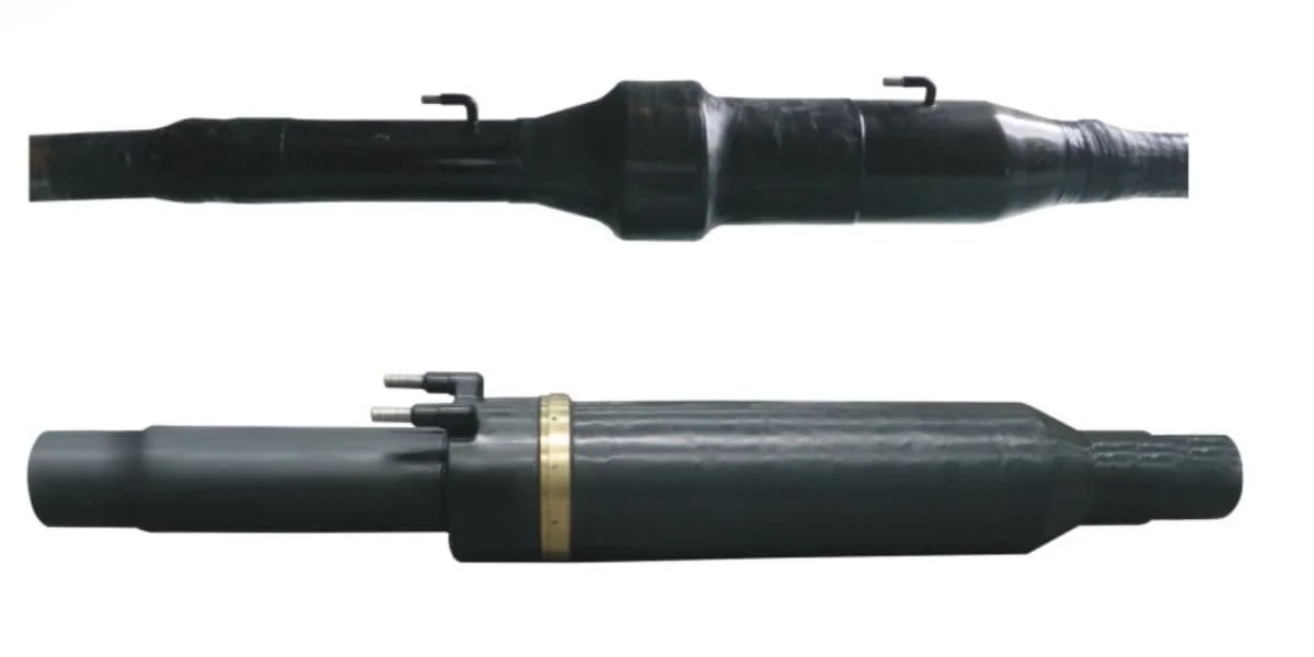
2. Corps d'isolation
The insulation body is one of the most important parts of a 110kV cable joint.
It restores the insulation between the conductor and the grounded metallic screen. Most modern prefabricated joints use high-quality silicone rubber or other specially designed insulating materials.
The insulation body must provide:
- Rigidité diélectrique élevée
- Performances électriques stables
- Good thermal resistance
- Reliable interface contact
- Long-term resistance to electrical ageing
The insulation body must also fit the cable dimensions accurately. Poor interface contact can cause air gaps, partial discharge, and electrical breakdown.
3. Contrôle des contraintes électriques
At the cable joint, the original cable insulation screen is interrupted. This creates an area where the electric field can become highly concentrated.
Donc, a 110kV cable joint needs an effective electrical stress control system.
The stress control structure helps distribute the electric field more evenly. It reduces electrical stress around the conductor connector and the insulation screen cutback.
A well-designed stress control system is essential for long-term operating reliability.
4. Metallic Screen and Grounding Components
The metallic screen or sheath provides an electrical return path and helps control the electric field around the cable insulation.
The joint must restore the required metallic continuity or provide the specified insulation arrangement, depending on the bonding design.
Par exemple, a cable system may use:
- Single-point bonding
- Both-end bonding
- Cross-bonding
The grounding arrangement must match the complete cable circuit design. Engineers should not select the grounding method based only on the joint accessory.
5. Outer Protection and Sealing
The outer protection system prevents water and moisture from entering the joint.
It may include a metallic casing, protective shell, sealing materials, and an external corrosion protection system.
For underground installations, the joint must withstand the actual environmental conditions. These may include groundwater, soil pressure, changements de température, et exposition chimique.
Reliable sealing is especially important for cable joints installed in underground joint bays or tunnels.
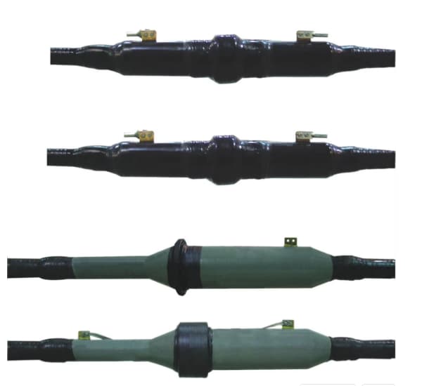
Types of 110kV Cable Joints
Different power transmission projects require different joint designs. The correct type depends on the cable structure, environnement d'installation, and electrical bonding arrangement.
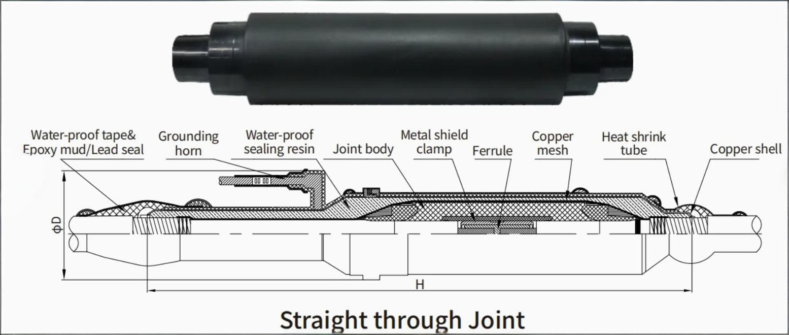
1. 110kV Straight Through Joint
A 110kV straight through joint connects two cables of the same voltage level. It maintains electrical continuity between the conductors and restores the cable insulation system.
This is one of the most common types of high-voltage cable joints.
Les applications typiques incluent:
- Underground transmission cable routes
- Réseaux urbains de distribution d’énergie
- Systèmes d'alimentation industrielle
- Substation cable connections
- Long-distance underground cable circuits
A straight through joint can be designed for copper or aluminum conductors. Cependant, the connector and joint components must match the actual cable specifications.
2. 110kV Insulating Joint
An insulating joint separates the metallic sheaths or screens of two cable sections electrically.
It is used when the cable bonding system requires electrical separation between different sections.
Par exemple, some cable systems use insulating joints as part of their sheath bonding arrangement. The design can help control induced sheath voltages and circulating currents.
The exact configuration depends on the cable circuit and grounding design.
3. 110kV Cross-Bonding Joint
Cross-bonding is commonly used in long high-voltage cable circuits.
In this arrangement, the metallic sheaths of cable sections are connected in a specific sequence. This helps reduce induced sheath voltages and circulating currents.
Cross-bonding systems normally require suitable cross-bonding link boxes and associated accessories.
The joint design must provide the required sheath connections and insulation separation. Engineers should consider the complete bonding system when selecting a 110kV cable joint.
4. 110kV Transition Joint
A transition joint connects two cables with different constructions or conductor materials.
Par exemple, a project may need to connect:
- Copper conductor cable to aluminum conductor cable
- Cables with different conductor cross-sections
- Cables with different metallic sheath designs
- Different approved cable insulation constructions
A transition joint requires special consideration of conductor connection, insulation geometry, and sheath continuity.
The manufacturer must confirm that the proposed design is suitable for both cable types.
Technical Specifications of a 110kV Cable Joint
The technical specifications of a 110kV cable joint depend on the cable design and project requirements.
The following table shows typical information required when preparing a technical specification.
| Paramètre | Exigence typique |
|---|---|
| Tension nominale | 64/110kV |
| Tension maximale du système (Un) | 123kV |
| Isolation des câbles | XLPE |
| Matériau conducteur | Cuivre ou aluminium |
| Section du conducteur | Spécifique au projet |
| Joint type | Straight through or insulating |
| Matériau isolant | Silicone rubber or approved insulating material |
| Connexion du conducteur | Compression or mechanical connector |
| Gaine métallique | According to cable design |
| Lieu d'installation | Intérieur, de plein air, underground or tunnel |
| Norme applicable | CEI 60840 |
| Essai | According to applicable standards and project specifications |
The table is a general reference, not a complete product datasheet. Actual dimensions, caractéristiques électriques, matériaux, and test requirements must be confirmed for each project.
Common 110kV Cable Conductor Sizes
110kV XLPE cables are available in different conductor cross-sections. The selection depends on the required current capacity, conditions de pose, and short-circuit requirements.
Les tailles de conducteurs courantes incluent:
| Conductor Cross-Section | Matériel |
|---|---|
| 240 mm² | Cuivre / Aluminium |
| 300 mm² | Cuivre / Aluminium |
| 400 mm² | Cuivre / Aluminium |
| 500 mm² | Cuivre / Aluminium |
| 630 mm² | Cuivre / Aluminium |
| 800 mm² | Cuivre / Aluminium |
| 1000 mm² | Cuivre / Aluminium |
| 1200 mm² | Cuivre / Aluminium |
| 1400 mm² | Cuivre / Aluminium |
| 1600 mm² | Cuivre / Aluminium |
| 2000 mm² | Cuivre / Aluminium |
| 2500 mm² | Cuivre / Aluminium |
Not every joint design covers all conductor sizes. The manufacturer must confirm the available range and the compatibility of the connector and insulation body with the selected cable.
Applicable Standards for 110kV Cable Joints
International standards are important when selecting a high-voltage cable joint. They define requirements for design, fabrication, essai, et performances électriques.
CEI 60840
CEI 60840 is one of the main international standards for high-voltage extruded insulation cable systems.
Its full title is:
Câbles d'alimentation à isolation extrudée et leurs accessoires pour tensions nominales supérieures à 30 kV (Un = 36 kV) jusqu'à 150 kV (Un = 170 kV) – Test methods and requirements.
This standard covers cable systems and accessories within its voltage range. A 110kV cable joint with a maximum system voltage of 123kV falls within this range.
It includes requirements for electrical tests and performance evaluation of cable accessories.
Other Relevant Standards
Selon le projet, other standards may also apply.
- CEI 60270: High-voltage test techniques – Partial discharge measurements.
- CEI 60885 series: Electrical test methods for electric cables, le cas échéant.
- CEI 60228: Conducteurs de câbles isolés.
- CEI 61442: Test methods for accessories for power cables with rated voltages from 6kV (Um = 7.2kV) up to 30kV (Um = 36kV). This standard does not cover 110kV joints.
For 110kV cable joints, CEI 60840 is the key product standard. The project specification may also require additional tests, approvals, or utility-specific requirements.
Manufacturing Process of a 110kV Cable Joint
Manufacturing quality has a direct impact on the performance of high-voltage cable accessories.
A professional 110kV cable joint manufacturer should control every important production stage.
1. Sélection des matériaux
The manufacturer selects suitable materials for the insulation body, connecteur de conducteur, stress control components, and protective system.
Material quality must meet the electrical, mécanique, and thermal requirements of the product.
2. Insulation Body Production
The insulation body is manufactured under controlled conditions.
For prefabricated joints, dimensional accuracy is especially important. The internal surface and interface quality must meet the approved design requirements.
3. Component Assembly
The manufacturer assembles the conductor connector, insulation body, stress control components, and other accessories according to the approved design.
Each component must fit correctly to avoid damage during installation.
4. Quality Inspection
The manufacturer checks the dimensions, material quality, and assembly condition.
Electrical tests and other inspections are then performed according to the approved test plan.
5. Packaging and Delivery
Enfin, the manufacturer protects the joint components against dust, humidité, et dommages mécaniques.
Each set should include the required installation instructions, component list, and technical documentation.
Installation of a 110kV Cable Joint
Correct installation is essential for the reliable operation of a 110kV cable joint.
Even a high-quality product can fail if the installation process is not properly controlled.
The installation should be carried out by trained high-voltage cable jointers.
Étape 1: Check the Cable and Joint
Avant l'installation, engineers should check the cable type, taille du conducteur, diamètre d'isolation, and metallic sheath structure.
They should also confirm that the joint kit matches the approved cable design.
Étape 2: Prepare the Cable Ends
The installers prepare both cable ends according to the manufacturer’les instructions.
This includes removing the outer sheath, écran métallique, écran isolant, and other layers at the specified positions.
The cutting dimensions must be accurate.
Étape 3: Connect the Conductors
The conductor connector joins the two cable conductors.
Installers must use the correct connector and approved compression or mechanical installation method.
They should also check the connector surface to ensure that no sharp edges or burrs remain.
Étape 4: Install the Insulation Body
The insulation body is installed over the conductor connection.
Installers must keep the insulation surfaces clean and follow the specified installation sequence.
Poussière, humidité, or improper positioning can affect the electrical performance of the joint.
Étape 5: Restore the Metallic Screen
The metallic screen and sheath connections are completed according to the cable bonding design.
For cross-bonded cable systems, installers must follow the approved connection diagram.
Étape 6: Complete Sealing and Protection
The external sealing and protective components are installed.
This step helps prevent water from entering the joint during long-term operation.
Étape 7: Perform Electrical Tests
Après l'installation, the cable system undergoes the required commissioning tests.
The test methods and voltage levels must follow the applicable standards and project specifications. The test plan should also consider the condition of the complete cable system.

Testing Requirements for 110kV Cable Joints
Testing helps confirm that the cable joint meets the required performance level.
The exact test program depends on the applicable standard, product design, et les exigences du projet.
Common test categories include:
1. Test de décharge partielle
Partial discharge testing helps identify insulation defects and electrical discharge activity.
It is an important part of high-voltage cable accessory evaluation.
2. AC Voltage Test
The AC voltage test checks the electrical insulation performance of the cable system and its accessories.
The test voltage and duration must follow the applicable standard and approved test procedure.
3. Impulse Voltage Test
Impulse testing evaluates the ability of the insulation system to withstand transient overvoltages.
It is particularly important for high-voltage cable accessories.
4. Heating Cycle Test
Heating cycle tests evaluate the performance of the cable system under repeated temperature changes.
They help assess the joint’s ability to operate under normal load conditions.
5. Routine and Quality Tests
Manufacturers should also perform the routine inspections and tests required by the product design and relevant standards.
Customers should request the applicable type-test reports, routine test records, and quality documents before approving a 110kV cable joint.
Applications of 110kV Cable Joints
110kV cable joints are widely used in modern power transmission networks.
Urban Underground Power Networks
Large cities often use underground high-voltage cables because overhead transmission lines are difficult to install in densely populated areas.
110kV cable joints connect cable sections along underground routes and help maintain reliable power transmission.
Power Substations
Substations use 110kV XLPE cables to connect transformers, Équipement SIG, and other electrical systems.
Cable joints may be required when cable routes contain multiple sections or when cable lengths are limited.
Installations industrielles
Large industrial plants require stable high-voltage power supplies.
Aciéries, chemical factories, installations minières, and manufacturing centers may use 110kV cable systems to transmit electricity from substations to major loads.
Projets d'énergie renouvelable
Wind farms and solar power plants may require high-voltage underground cable connections.
110kV cable joints can be used in suitable transmission and collection systems, depending on the project voltage design.

How to Select a Reliable 110kV Cable Joint Manufacturer
Choosing the right manufacturer is important for project safety and long-term reliability.
Customers should consider several factors before placing an order.
1. High-Voltage Product Experience
The manufacturer should have experience in producing high-voltage cable accessories.
Experience with 110kV and 123kV cable systems is particularly relevant.
2. Complete Cable Compatibility
The manufacturer should review the actual cable datasheet before recommending a joint.
Important information includes conductor material, conductor cross-section, diamètre d'isolation, épaisseur d'isolation, metallic sheath, and outer sheath structure.
3. Type-Test Reports
Customers should request valid type-test reports that match the proposed joint design and voltage class.
A test report for a different product design or voltage rating should not automatically be considered proof of compliance.
4. Assistance à l'installation
A reliable supplier should provide detailed installation instructions and technical support.
For important transmission projects, experienced installation supervision can also help reduce installation risks.
5. Project Customization
Different projects may require different joint structures.
Par exemple, some customers need straight through joints, while others require insulating joints or cross-bonding arrangements.
The manufacturer should be able to review project requirements and provide a suitable technical proposal.
Information Required for a 110kV Cable Joint Quotation
To prepare an accurate quotation, customers should provide the following information:
- Tension nominale: 64/110kV or another specified voltage.
- Matériau conducteur: Cuivre ou aluminium.
- Section du conducteur: Par exemple, 630mm², 800mm², 1000mm² or 1600mm².
- Isolation des câbles: XLPE.
- Cable insulation diameter and thickness.
- Metallic sheath material and structure.
- Joint type: Straight through, insulating, or cross-bonding.
- Environnement d'installation: Souterrain, tunnel, indoor, or outdoor.
- Applicable standards and project specifications.
- Required quantity and delivery location.
Providing complete cable information helps the manufacturer select the correct joint design and avoid compatibility problems.
Frequently Asked Questions About 110kV Cable Joints
1. What is the maximum system voltage of a 110kV cable joint?
A typical 110kV cable system has a rated voltage of 64/110kV and a maximum system voltage of 123kV (Un). The joint must be designed and tested for the applicable voltage class.
2. What standard applies to 110kV cable joints?
CEI 60840 is the main international standard for extruded-insulation cable systems and accessories above 30kV up to 150kV, within its specified maximum system voltage range.
3. Can a 110kV cable joint connect copper and aluminum cables?
Oui, a specially designed transition joint can connect copper and aluminum conductors. Cependant, the connector must be suitable for both conductor materials and the complete joint design must meet the required electrical and mechanical performance.
4. What is the difference between a straight through joint and an insulating joint?
A straight through joint connects two cable sections and maintains the required electrical continuity. An insulating joint provides electrical separation between specified metallic sheath or screen sections.
5. How long is the service life of a 110kV cable joint?
The service life depends on the joint design, material quality, manufacturing process, installation quality, and operating conditions. A properly designed and installed joint can provide long-term service within the expected life of the cable system.
6. Does a 110kV cable joint require a link box?
Not every 110kV cable joint requires a link box. A link box is commonly used in cable sheath bonding systems, especially for single-point bonding and cross-bonding arrangements. The requirement depends on the cable circuit design.
Dosense Cable – 110kV Cable Joint Manufacturer
Dosense Cable is a manufacturer of power cables and cable accessories. We focus on high-voltage cable solutions for power transmission, sous-stations, installations industrielles, et projets d'infrastructures.
For 110kV cable systems, selecting the correct cable joint is essential for safe and reliable operation. The joint must match the cable conductor, insulation dimensions, metallic sheath structure, and electrical bonding arrangement.
Dosense Cable can work with customers to review project specifications and provide technical solutions for 110kV cable joints. Whether your project requires a 110kV straight through joint, insulating joint, or a customized XLPE cable joint, our team can support your technical evaluation and quotation requirements.
Contact Dosense Cable with your cable datasheet and project specifications to discuss a suitable 110kV Cable Joint solution.