
1. Introduction to 145kV Cable GIS Termination
A 145kV Cable GIS Termination is a high-voltage cable accessory designed to connect underground power cables to Gas Insulated Switchgear (SIG) in high-voltage transmission and distribution systems. It provides a reliable electrical connection between the XLPE insulated power cable and the GIS equipment while maintaining the required insulation performance and electrical safety.
In modern power transmission networks, GIS substations are widely used because of their compact design, high operational reliability, and reduced installation space. Compared with conventional air-insulated substations, GIS equipment uses SF6 gas or alternative insulating gases to provide electrical insulation between live components and grounded metal enclosures.
The connection between a high-voltage cable and GIS equipment is particularly important. A properly designed 145kV GIS cable termination must control the electric field, prevent partial discharge, maintenir l’intégrité de l’isolation, and ensure stable electrical contact throughout its service life.
For 145kV transmission systems, GIS cable terminations are commonly used with XLPE underground cables in substations, centrales électriques, urban transmission networks, and industrial power supply projects.
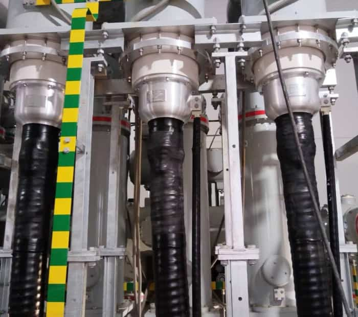
2. What Is a 145kV GIS Cable Termination?
A GIS cable termination is a specialized cable accessory installed at the end of a high-voltage cable to connect it to gas-insulated switchgear.
Unlike conventional outdoor cable terminations, which are exposed to atmospheric conditions, a GIS termination is installed inside a sealed GIS cable compartment. Its connection interface must match the corresponding GIS equipment design.
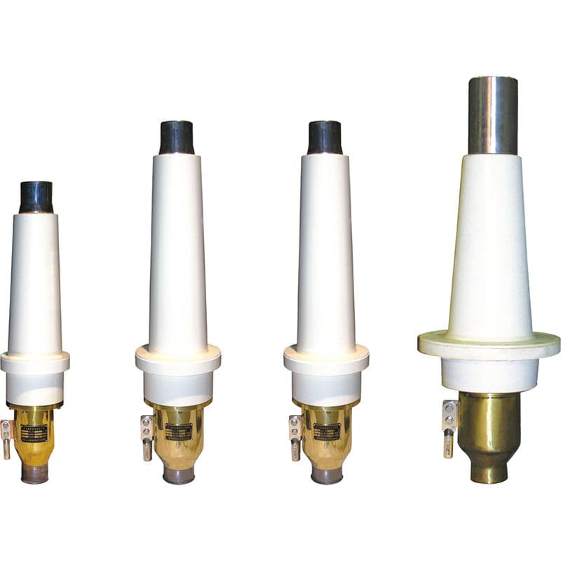
A typical 145kV cable GIS termination consists of several main components:
- Stress control system
- Corps isolant
- Epoxy resin insulator
- Electrical connector
- Cable conductor connection
- Cable sealing components
- Grounding and shielding components
- GIS connection interface
The main function of the termination is to provide a smooth transition of electrical insulation from the XLPE cable to the GIS equipment.
At the end of an XLPE cable, the metallic screen and semiconductor layers are removed in a controlled manner. This creates a high electric field concentration near the insulation screen cutback. Without an appropriate stress control system, this area may experience excessive electrical stress, which can lead to partial discharge and insulation failure.
The GIS termination uses a specially designed stress control structure to distribute the electric field evenly and maintain reliable insulation performance.
3. Main Structure of a 145kV Cable GIS Termination
The design of a 145kV GIS cable termination depends on the cable specifications, Interface SIG, tension nominale, and installation requirements.
The following components are commonly included.
3.1 Epoxy Resin Insulator
The epoxy resin insulator is one of the most important parts of a GIS cable termination.
It provides the main insulating barrier between the high-voltage conductor and the grounded GIS enclosure. High-quality epoxy resin offers excellent dielectric properties, force mécanique, and dimensional stability.
The epoxy insulator is designed to withstand the electrical stresses generated during normal operation and overvoltage conditions.
Its interface dimensions must be compatible with the GIS equipment.
3.2 Stress Control Component
The stress control system reduces the electric field concentration at the cable insulation screen cutback.
Depending on the termination design, stress control may use specially engineered insulating and semiconductive materials, including prefabricated stress cones.
Proper stress control is essential for preventing partial discharge and improving the long-term reliability of the cable connection.
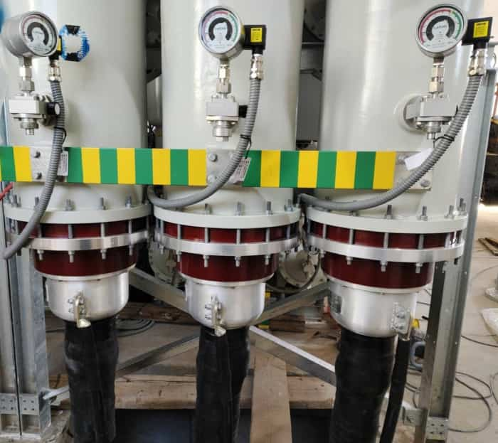
3.3 Electrical Connector
The electrical connector connects the cable conductor to the GIS conductor system.
It can be designed for copper or aluminum cable conductors. The connector must provide sufficient electrical contact pressure and low contact resistance.
For large cross-section cables, the conductor connection method, connector dimensions, and installation tools should be confirmed before production.
3.4 Insulating and Sealing Components
Insulating and sealing components prevent moisture, gas leakage, and other environmental factors from affecting the connection.
The sealing system is especially important because GIS equipment operates within a sealed gas compartment.
The termination design must match the GIS manufacturer’s specified sealing arrangement.
3.5 Grounding and Metallic Shielding
The cable metallic screen and grounding system must be correctly connected according to the project grounding design.
Depending on the cable system, grounding arrangements may include single-point bonding, both-end bonding, or cross-bonding.
The grounding configuration should be confirmed through the cable system design rather than determined by the termination alone.
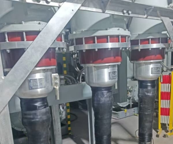
4. Working Principle of a 145kV GIS Cable Termination
The working principle of a GIS termination is based on electrical field control and insulation coordination.
When high voltage is applied to the cable conductor, the electric field is distributed through the XLPE insulation. Au bout du câble, the insulation screen is removed to expose the conductor connection area.
This creates a discontinuity in the cable’s electrical shielding structure.
The GIS termination compensates for this discontinuity through its stress control system and specially designed insulation structure.
The main functions include:
- Controlling the electric field at the cable insulation screen cutback.
- Providing reliable insulation between the high-voltage conductor and grounded GIS enclosure.
- Maintaining a stable electrical connection between the cable and GIS.
- Preventing partial discharge under specified operating conditions.
- Maintaining insulation performance during normal operation and electrical stress conditions.
The design must also consider thermal expansion, mechanical forces, fiabilité de la connexion des conducteurs, and the operating environment of the substation.
5. Technical Specifications of 145kV GIS Cable Termination
The technical specifications of a 145kV cable GIS termination should be customized according to the cable and GIS equipment requirements.
A typical project specification may include the following information:
| Paramètre | Typical requirement |
|---|---|
| Produit | Terminaison de câble SIG |
| Tension nominale (Un) | 145kV |
| Isolation des câbles | XLPE |
| Cable conductor | Cuivre ou Aluminium |
| Cable cores | Single-core |
| Lieu d'installation | Indoor GIS substation |
| Termination type | Dry-type plug-in |
| Matériau isolant | Epoxy resin and silicone rubber, selon la conception |
| Section du conducteur | Spécifique au projet |
| Diamètre d'isolation du câble | Spécifique au projet |
| Interface SIG | According to GIS manufacturer |
| Normes applicables | CEI 60840, CEI 62271-209, as applicable |
| Operating frequency | 50Hz or 60Hz |
Important: The above table is a general reference, not a universal dimensional or performance specification. The actual rated voltage notation, cable dimensions, Interface SIG, and electrical test requirements must be confirmed for each project.
Par exemple, a 145kV system may use a cable rated 76/132(145)kV. The cable insulation diameter and GIS connection interface must be checked before manufacturing.
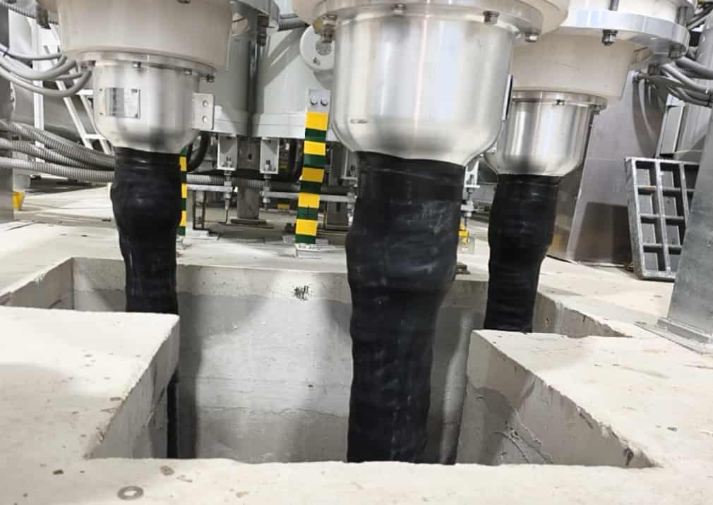
6. Dry-Type GIS Termination vs. Terminaison SIG remplie d'huile
Different GIS cable connection technologies are available depending on the equipment design and project requirements.
Dry-Type GIS Cable Termination
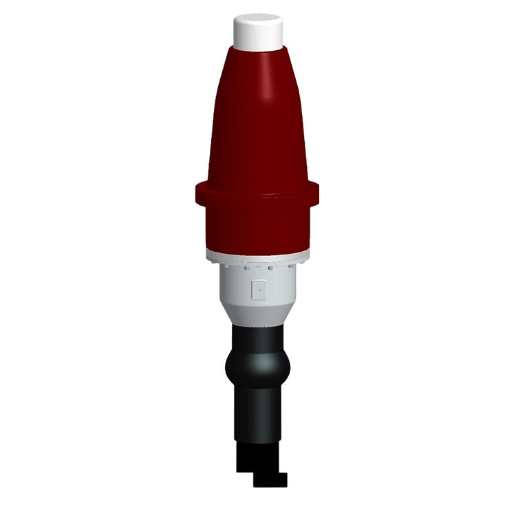
Dry-type GIS terminations commonly use prefabricated solid insulation components, such as silicone rubber stress cones and epoxy resin insulators.
Les avantages incluent:
- No insulating oil filling is required.
- Reduced risk of oil leakage.
- Compact structure.
- Convenient installation and maintenance.
- Suitable for modern GIS substations.
Dry-type plug-in GIS terminations are widely used in modern high-voltage cable connection systems.
Oil-Filled GIS Cable Termination
Some older or specially designed GIS connection systems use oil-filled cable termination structures.
These designs rely on insulating oil to provide electrical insulation and may require additional oil containment and monitoring arrangements.
The choice between dry-type and oil-filled designs depends on the GIS manufacturer’s equipment configuration and the technical requirements of the project.
For new projects, dry-type solutions are often preferred where the GIS interface supports this technology.
7. Installation Procedure for 145kV GIS Cable Termination
Correct installation is essential for the electrical performance and service life of a high-voltage GIS termination.
Because 145kV is a high-voltage application, installation should only be carried out by qualified cable jointing technicians following the approved manufacturer’s installation manual.
A typical installation procedure includes the following steps:
Étape 1: Préparation des câbles
Check the cable type, taille du conducteur, diamètre d'isolation, écran métallique, and cable condition. Confirm that the cable length and installation space are sufficient.
Étape 2: Cable Cutting and Stripping
Cut the cable to the required length. Retirez la gaine extérieure, écran métallique, literie, and other cable layers according to the installation drawings.
Étape 3: XLPE Insulation Preparation
Carefully remove the outer semiconductive layer and prepare the XLPE insulation surface. The insulation surface must be smooth, clean, and free from scratches or contamination.
Étape 4: Install Stress Control Components
Install the prefabricated stress cone and other insulation components according to the manufacturer’s specified dimensions and procedures.
Étape 5: Connexion du conducteur
Connect the cable conductor to the specified electrical connector. The connection must comply with the required crimping or bolting procedure.
Étape 6: Install the GIS Termination Assembly
Assemble the termination body and connect it to the GIS cable compartment. Check the alignment, insertion depth, composants d'étanchéité, and interface compatibility.
Étape 7: Grounding and Final Inspection
Complete the cable metallic screen and grounding connections. Inspect all mechanical and electrical connections before commissioning.
Étape 8: Electrical Testing and Commissioning
Perform the required electrical tests according to the approved project specification and applicable standards.
The installation process may vary according to the GIS interface and termination manufacturer. Exact stripping dimensions and assembly procedures must always follow the supplied installation manual.
8. Applicable International Standards and Testing
Quality control is critical for 145kV GIS cable terminations because any insulation defect may cause serious equipment failure.
The following international standards are particularly relevant:
- CEI 60840: Power cables with extruded insulation and their accessories for rated voltages above 30kV up to 150kV.
- CEI 62271-209: Cable connections for gas-insulated metal-enclosed switchgear for rated voltages above 52kV.
- CEI 60270: High-voltage test techniques – Partial discharge measurements.
- CEI 60060: High-voltage test techniques.
The applicable edition and scope of each standard should be checked against the project requirements.
Typical quality control and testing activities include:
Test de décharge partielle
Partial discharge testing evaluates the insulation quality of the termination and helps identify internal defects or insulation weaknesses.
AC Withstand Voltage Test
This test verifies the ability of the termination insulation system to withstand the specified power-frequency test voltage.
Impulse Voltage Test
Lightning impulse testing evaluates the insulation system under transient overvoltage conditions.
Interface Inspection
The GIS connection interface must be checked for dimensional accuracy, surface quality, and compatibility with the GIS equipment.
Material Inspection
Insulating materials, epoxy resin components, composants en caoutchouc de silicone, and electrical connectors should be inspected according to the approved quality plan.
The actual test voltages, acceptance criteria, and test sequence must follow the applicable standards and approved type-test or project documentation.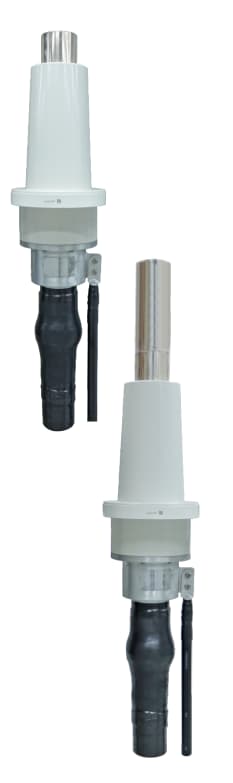
9. Applications of 145kV GIS Cable Termination
145kV GIS cable terminations are used in a wide range of high-voltage power transmission applications.
Les applications courantes incluent:
- Power transmission substations: Connecting underground XLPE cables to GIS equipment in high-voltage substations.
- Urban power networks: Supporting underground transmission systems where land availability is limited.
- Centrales électriques: Connecting generator step-up transformer systems and transmission networks where the GIS arrangement requires cable connections.
- Installations industrielles: Supplying electricity to large industrial plants, steel mills, petrochemical facilities, and mining projects.
- Projets d'énergie renouvelable: Connecting wind farms, solar power plants, and other renewable energy facilities to high-voltage substations.
- Underground cable systems: Providing reliable connections between underground transmission cables and GIS switchgear.
Compared with conventional air-insulated equipment, GIS substations offer a compact installation footprint, making them suitable for urban areas and locations with limited space.
10. How to Select the Right 145kV GIS Cable Termination
Selecting a suitable GIS cable termination requires more than simply confirming the voltage level.
Before purchasing, project engineers and procurement teams should check the following information:
- Tension nominale: Confirm the system voltage and cable rated voltage, tel que 76/132(145)kV.
- Cable conductor: Specify copper or aluminum conductors.
- Section du conducteur: Confirm the actual cable size, such as 400mm², 630mm², 800mm², or 1000mm².
- Diamètre d'isolation du câble: This is a critical dimension for termination compatibility.
- Construction de câbles: Provide the cable manufacturer’s datasheet and cross-sectional drawing.
- Fabricant de SIG: Identify the GIS manufacturer and equipment model.
- Interface SIG: Confirm the required connection type and interface dimensions.
- Conditions de pose: Specify the installation space, cable arrangement, and grounding requirements.
- Exigences de test: Confirm the applicable IEC standards and project-specific acceptance criteria.
Providing accurate cable and GIS information at the quotation stage can reduce design errors, shorten delivery time, and improve project compatibility.
11. 145kV GIS Cable Termination Manufacturer and Supplier – DOS Group
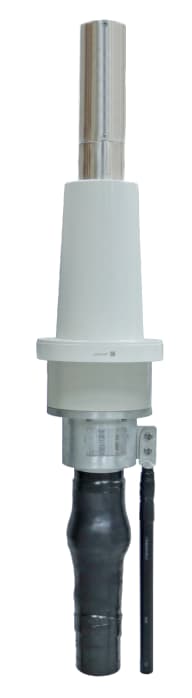
DOS Group is a professional manufacturer and supplier of high-voltage cable accessories and power transmission products in China.
We provide cable termination solutions for high-voltage and extra-high-voltage cable systems, including GIS cable terminations, outdoor cable terminations, indoor cable terminations, joints de câbles, and related accessories.
Our product range covers different voltage levels and cable configurations for power utilities, Entrepreneurs EPC, electrical engineering companies, and international power transmission projects.
For 145kV GIS cable termination projects, we can provide customized solutions according to the cable specifications and GIS equipment interface requirements.
Our engineering team can assist customers with:
- Technical drawings and product datasheets.
- Copper and aluminum conductor connection solutions.
- GIS interface compatibility confirmation.
- XLPE cable dimension matching.
- Installation manuals and technical support.
- Quality inspection and applicable test documentation.
Whether you are purchasing 145kV GIS cable terminations for a new substation, an underground transmission project, or a power grid upgrade, DOS Group can provide professional technical support and customized cable accessory solutions.
Contact DOS Group to discuss your 145kV Cable GIS Termination requirements and request a technical proposal or quotation.